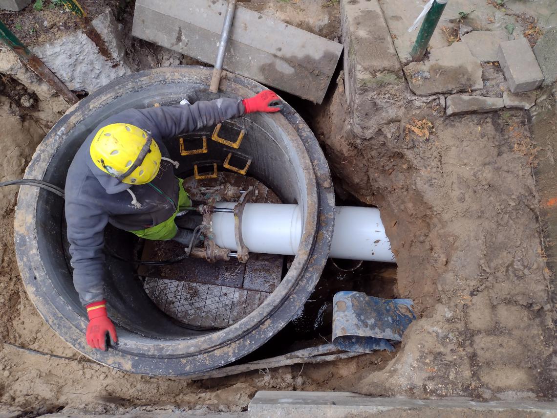
Implementation of the project: Construction of a water supply and sanitary sewage system in Kasprowicza street in Gdynia.
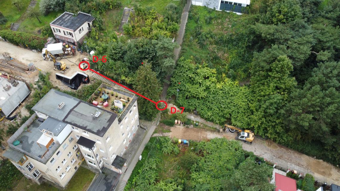
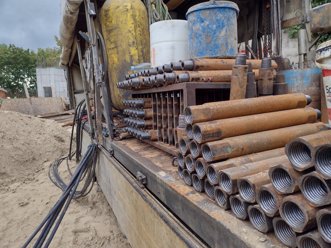
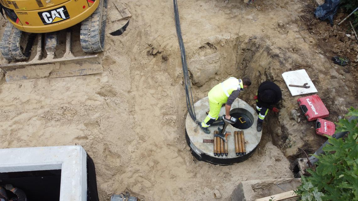
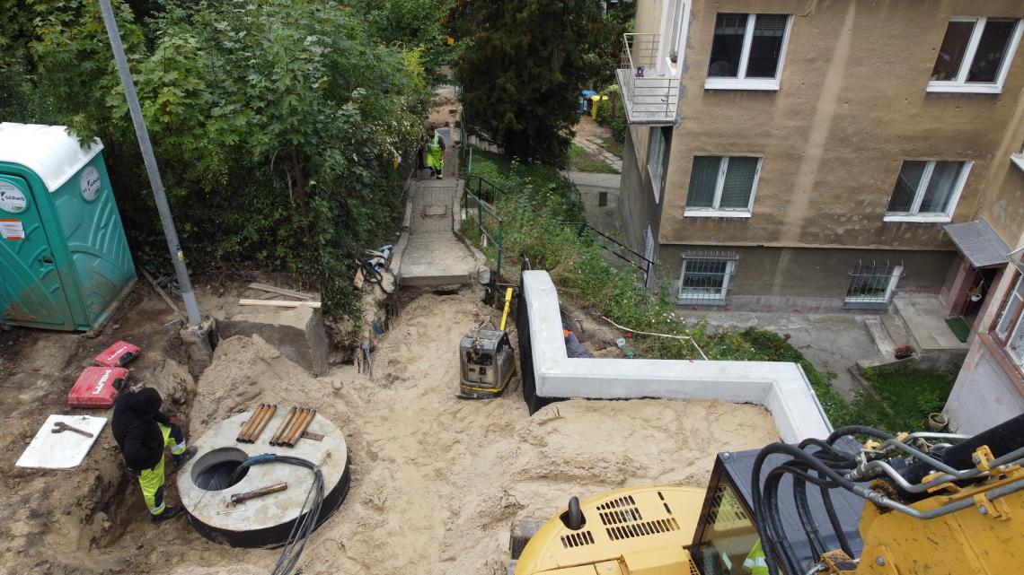
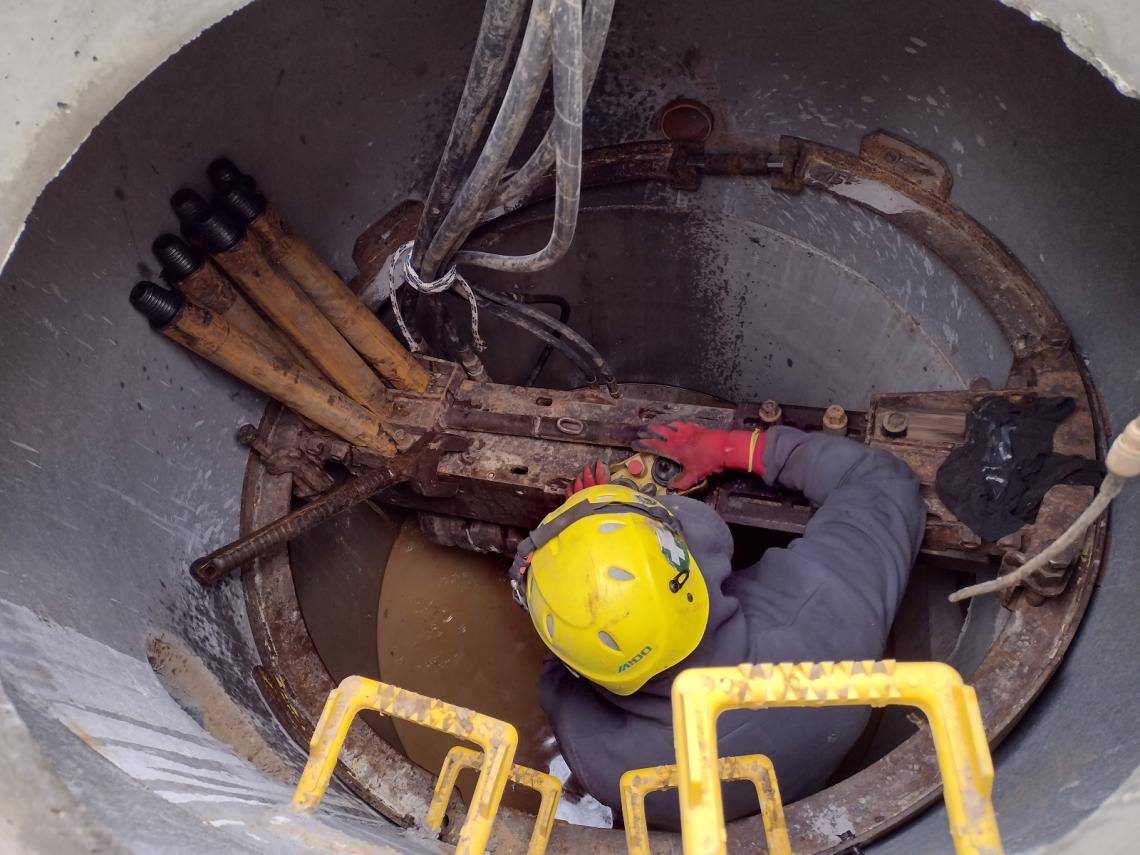
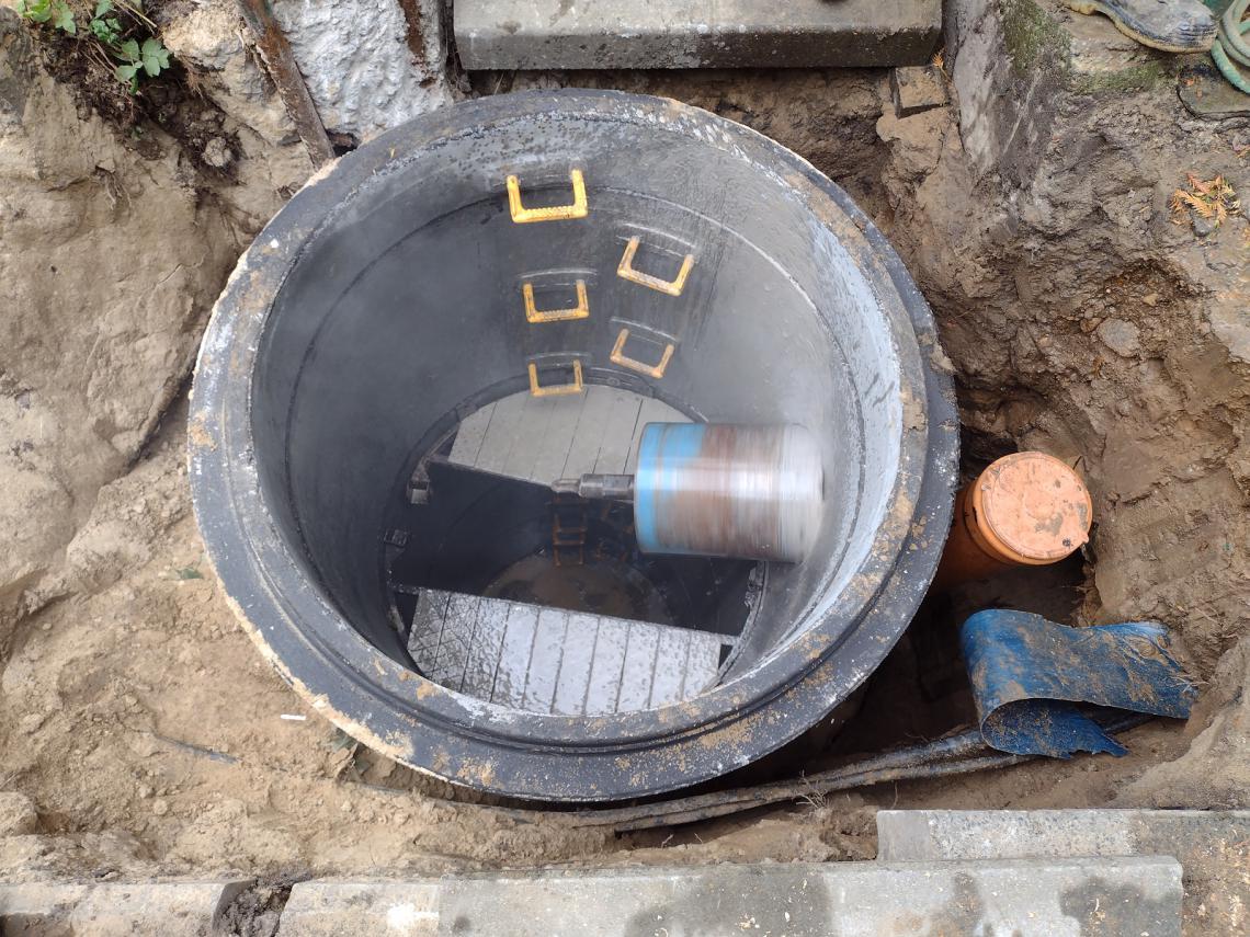
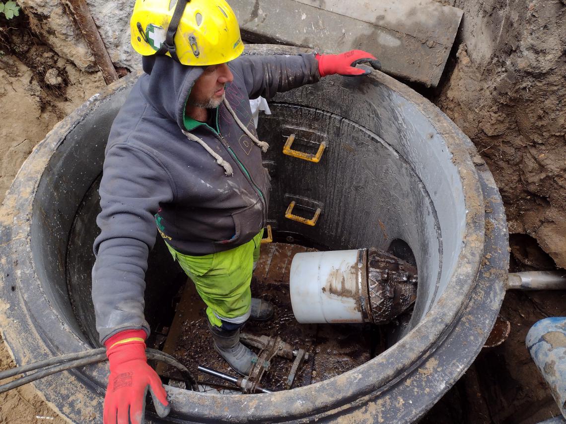
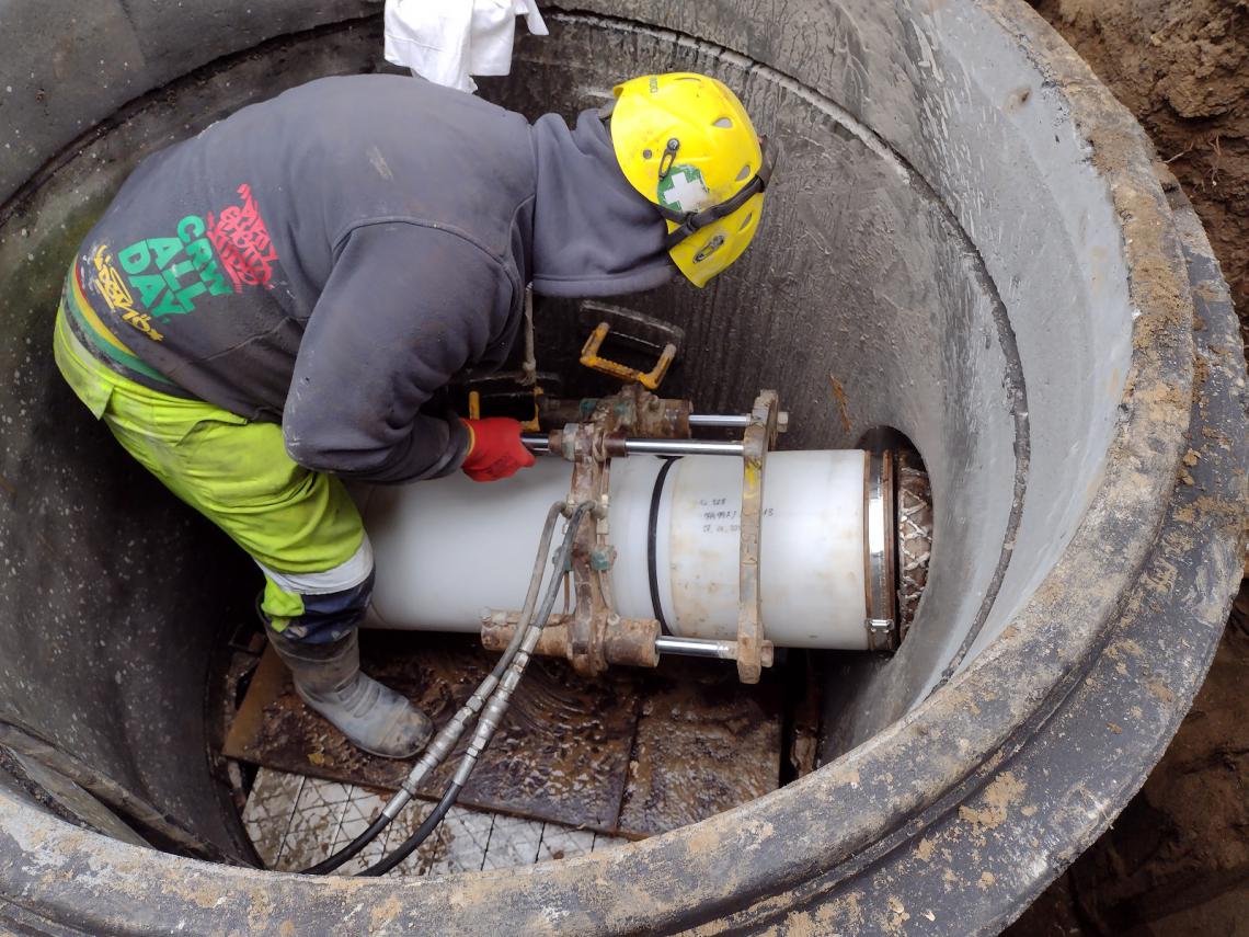
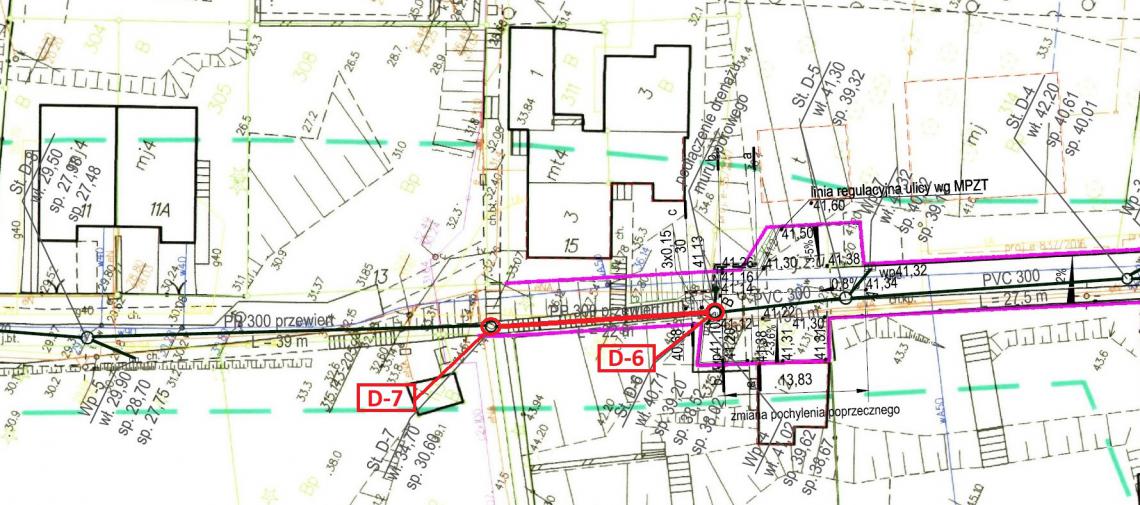
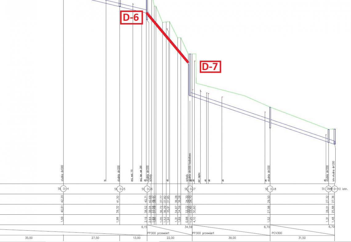
The scope of work included the execution of the rainwater drainage system, the section from the D-6 well to the D-8 well, through the D-7 well and the sanitary sewage system from the S-2 well to the S-3 well. As part of the entire task, trenchless laying of the channel was made of modular pipes PP 225x13.8x600 / 700 and 315x17.9x600 / 700. The total length of the rainwater drainage system made with the use of pipe 315 is approximately 60 meters. The total length of the sanitary installation performed using the 225 pipe is approximately 35 meters. The following study concerns the construction of a fragment of the rainwater system from the D-6 well to the D-7 well.
There are utilities in the construction section of the storm water drainage system:
- sanitary sewage system,
- waterworks,
- telecommunications cables,
- power cables,
- gas pipelines,
- district heating channel
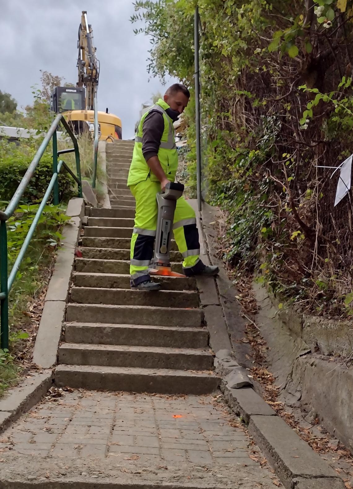
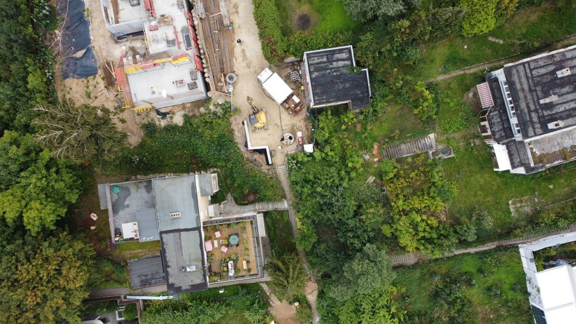
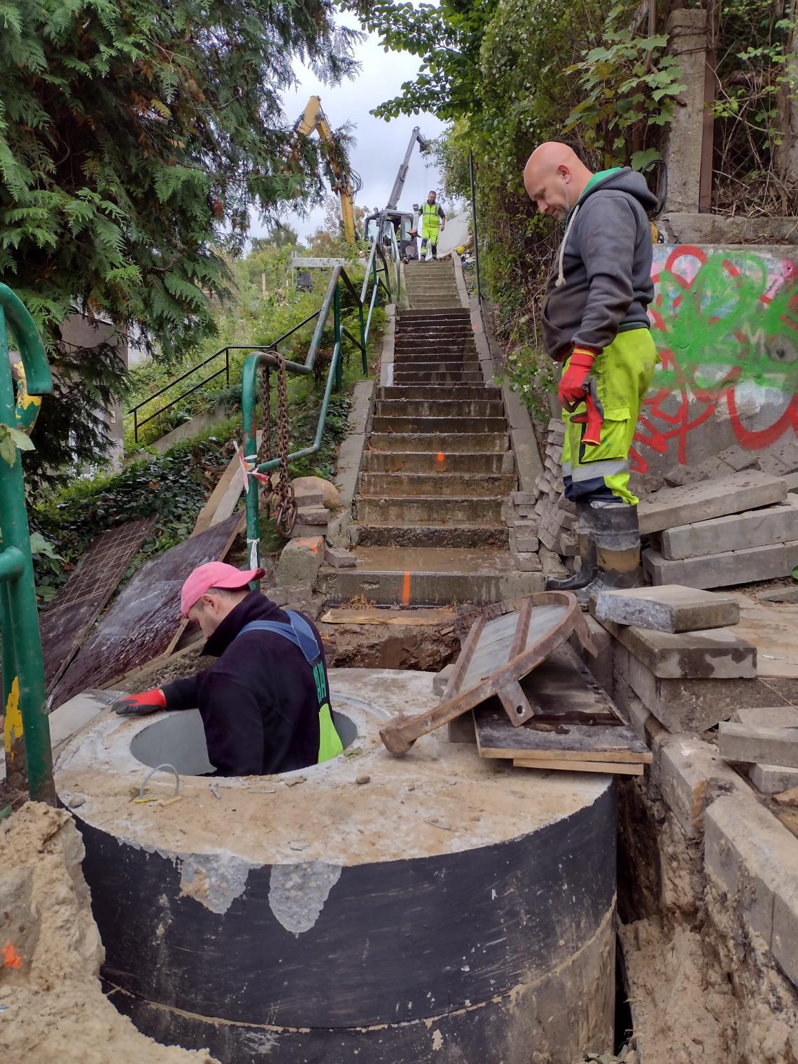
The route of the construction of the rainwater canal is marked on the roads and under the all-terrain stairs. The following parameters were adopted for the example section D-6 -> D-7:
F = 0,39 + 0,2 = 0,59ha
Q = 0,59 x 0,4 x 174 = 41,0 dm3/s
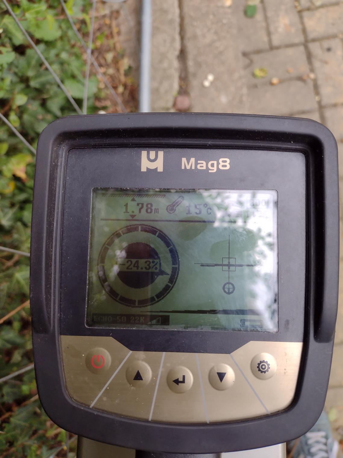
i = 24,0 %
Ø 0,30m
t = 5 cm
V = 6,0 m/s
The construction site was located in the vicinity of the seaside strip and the beach in Gdynia Redłowo. Despite the fact that, on the basis of the Regulation of the Minister of Transport, Construction and Maritime Economy of April 25, 2012, that the ground conditions in the investment area belong to the simple category, the construction area was classified as the second geotechnical category due to the depth of foundation of the installation.