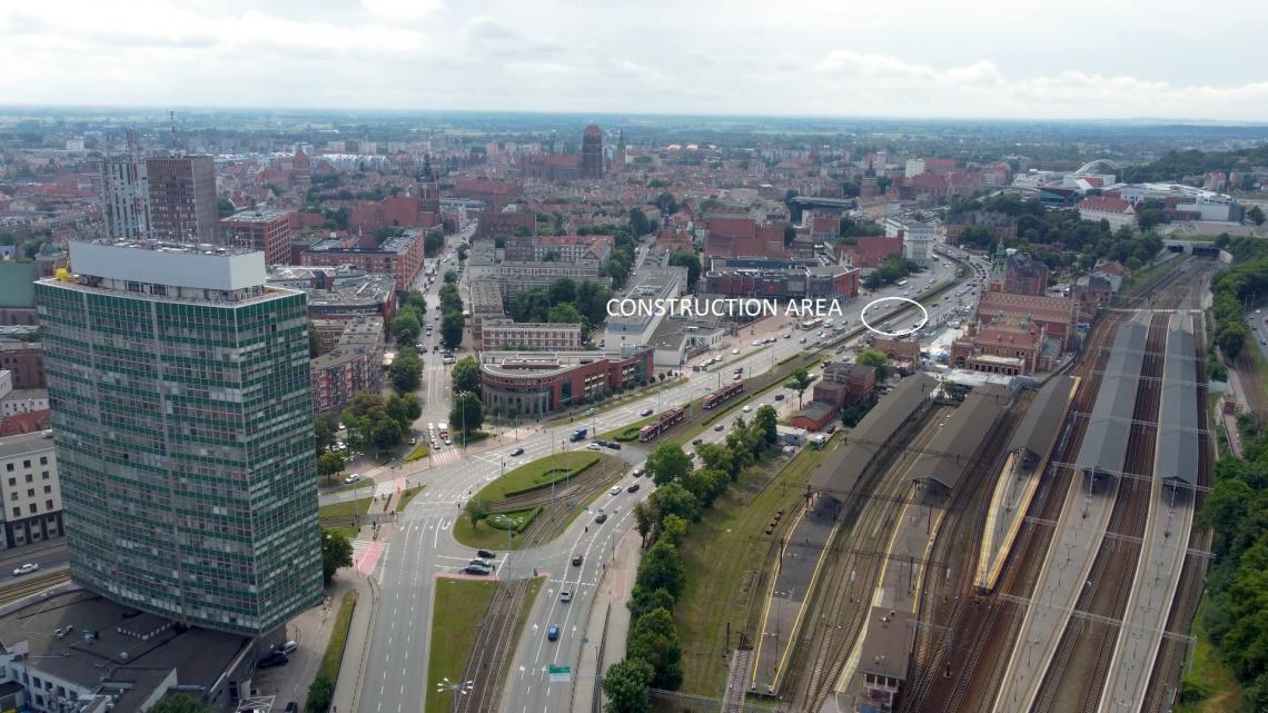
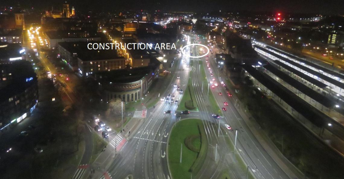
Renovation of the rainwater drainage system in Gdańsk at Podwale Grodzkie Street, as part of the project "Renovation of sections of the rainwater drainage system in Powstańców Warszawskich, Podwale Grodzkie and Grunwaldzka Streets in Gdańsk".
The scope of work included:
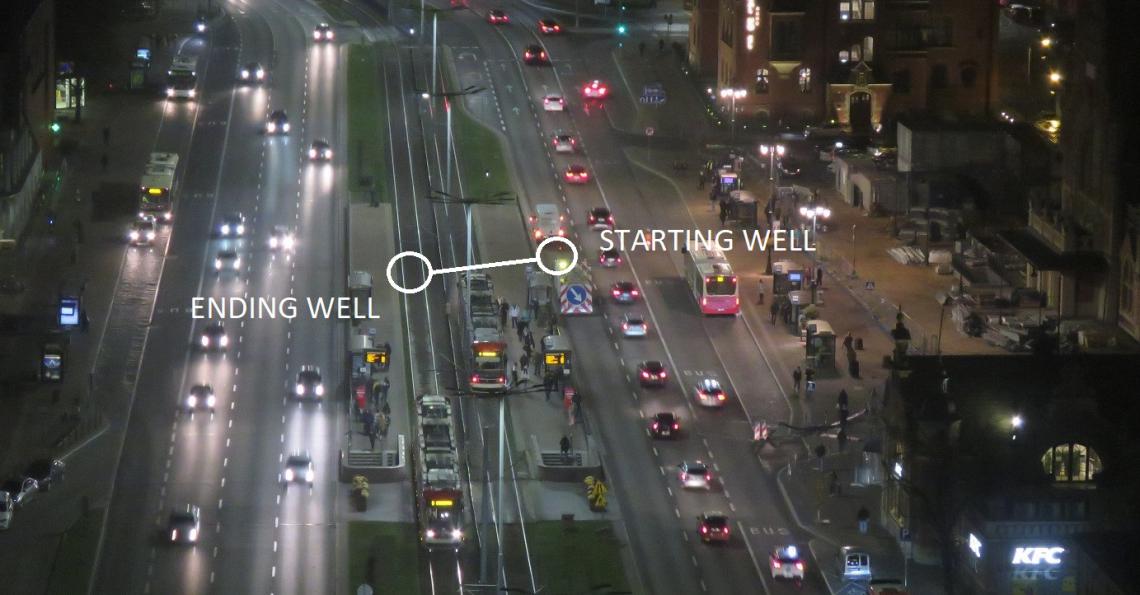
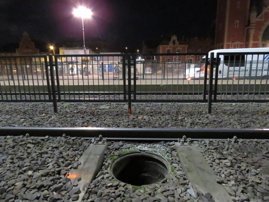
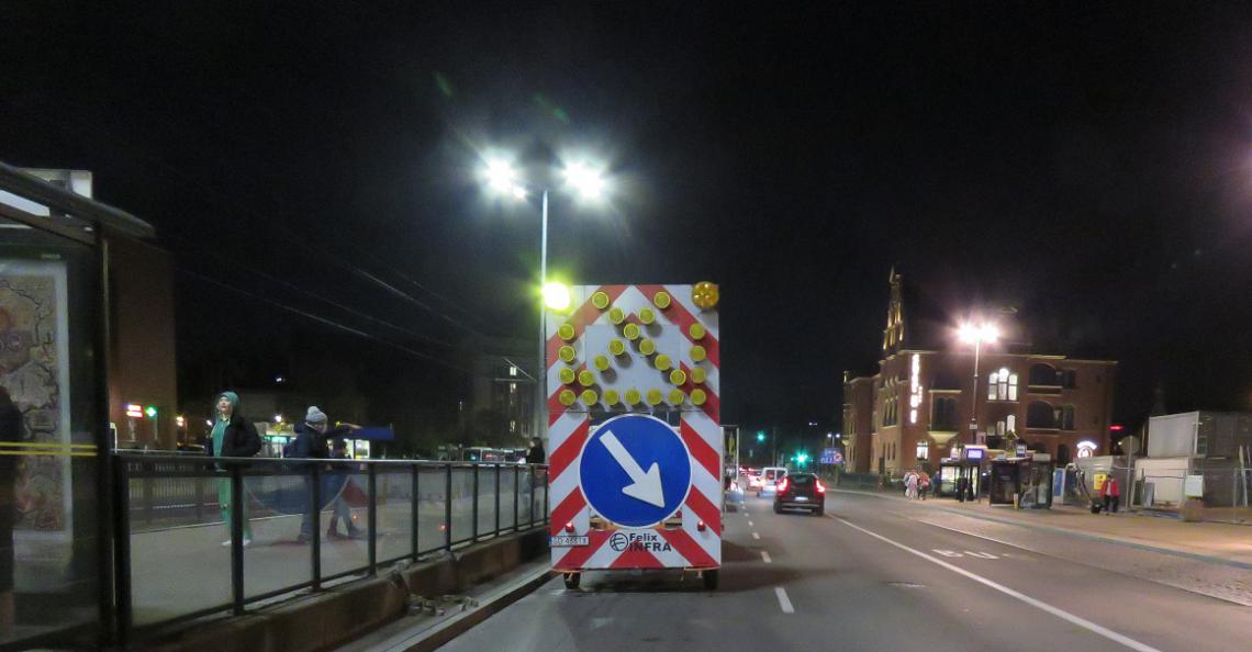
- preparation and agreement of temporary traffic organization and obtaining the consent of the road administrator to occupy the lane (note: the end well on the tram tracks),
- securing the work site (canal and side connections) by ensuring controlled drainage of rainwater during the shutdown period of the KD section, so that no flooding occurs during the execution of the works,
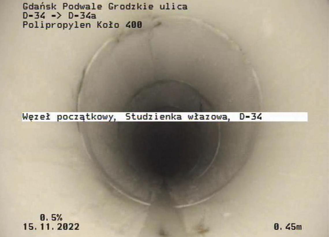
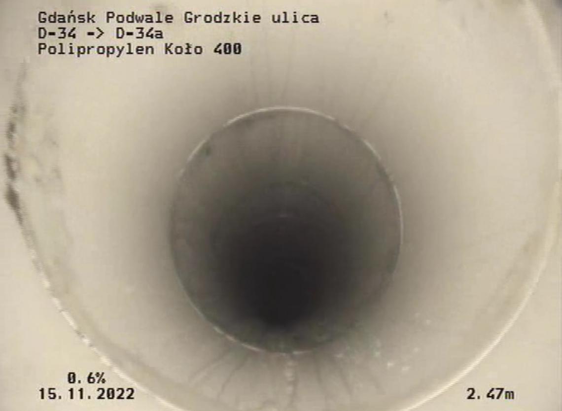
- pre-execution CCTV television inspection,
- pipeline cleaning,
- taking measurements before starting work,
- injecting the entire section of the canal with filling all free spaces,
- drilling and installation of a new pipe following the traces of the old sewer,
- as-built CCTV inspection,
- tidying up the place of work,
- preparation of as-built documentation.
The project consisted in a trenchless arrangement of a channel made of PP 400x22.7 modular pipes in place of a damaged channel located between the existing sewage chambers. The works had to be carried out using the existing wells and without making an open excavation and without damaging the surface. The renovation had to be carried out along the existing sewage route.
The difficulty in carrying out this task resulted from two important issues:
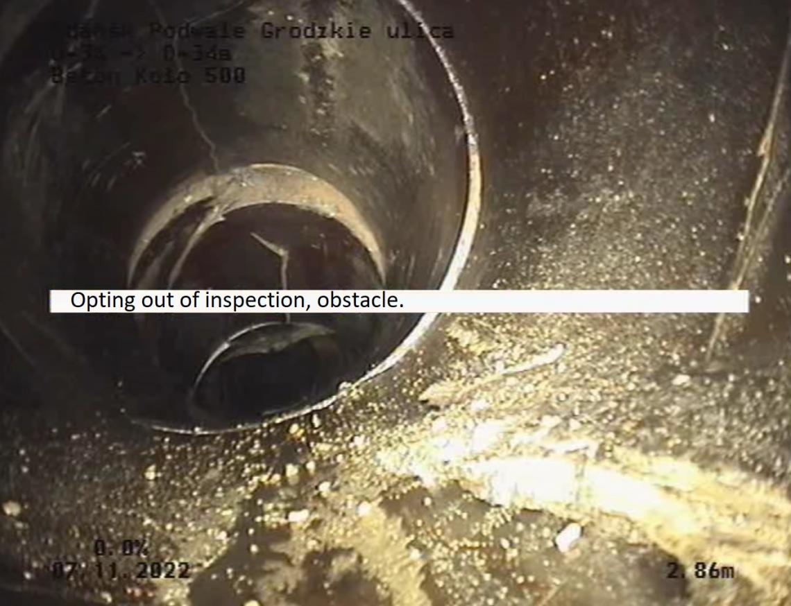
The damaged channel was COMPLETELY clogged.
The entire project included the renovation of four sections of the canal between the existing sewage chambers. Three of them were implemented by BLEJKAN using the technology of renovation with fiberglass sleeve lining. Unfortunately, the last section, located at Podwale Grodzkie Street, was blocked and damaged to such an extent that it was impossible to perform an inspection with a system with an inspection camera.
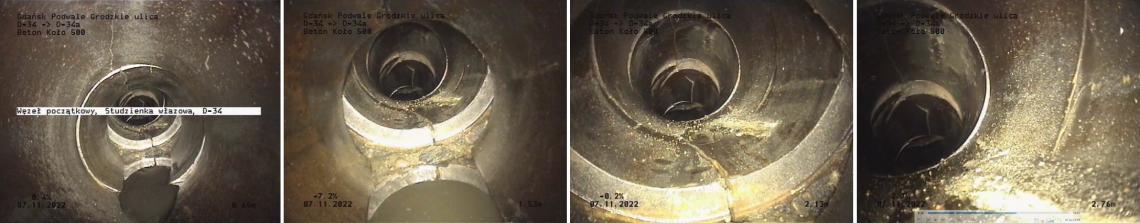
After less than three meters and encountering unique obstacles in the form of bends in the existing canal, the inspection had to be stopped. Otherwise, we risked losing valuable CCTV inspection equipment. The poor technical condition precluded the renovation technology with the use of a glass fiber sleeve lining.
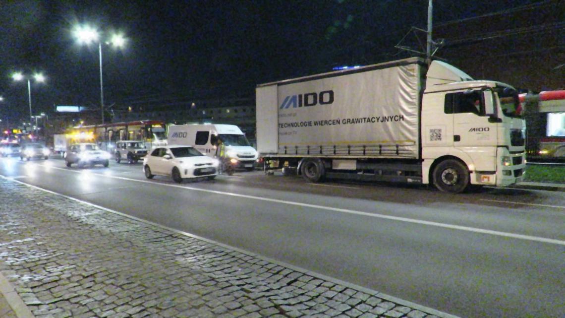
In addition, the contracting authority, for obvious reasons, did not allow the renovation method in the form of cracking. First of all, the damaged pipeline had to be strengthened by filling it with injection grout before its reconstruction. With the existing sewage pipe so severely damaged, the lack of this operation, combined with the additional impact of vibrations during the cracking renovation, guaranteed a construction disaster with its consequences in the form of losses counted in millions of euros. The pre-construction CCTV inspection showed us that the existing sewer is so damaged, which means that the ground around it is very unstable, full of voids and loose fractions. Rehabilitation using Cracking or a similar trenchless method would result in inevitable vibration-induced collapse of both the sewer itself and the ground around and above it. As a result, the main road in Gdańsk and the adjacent tram track, which is an important communication link between the city center and its western part, would collapse. In the case of renovation of such damaged networks, our technology includes filling with injection grout in the first process in order to obtain a stable space in the place of the damaged sewage pipe. In the next stages, corrective actions are taken. Another significant problem was the work site itself, the construction site. Podwale Grodzkie Street, and in particular its part adjacent to the Gdańsk Główny Railway Station, is one of the main transport hubs. The starting well was located on the extreme left lane of the three-lane Podwale Grodzkie street.

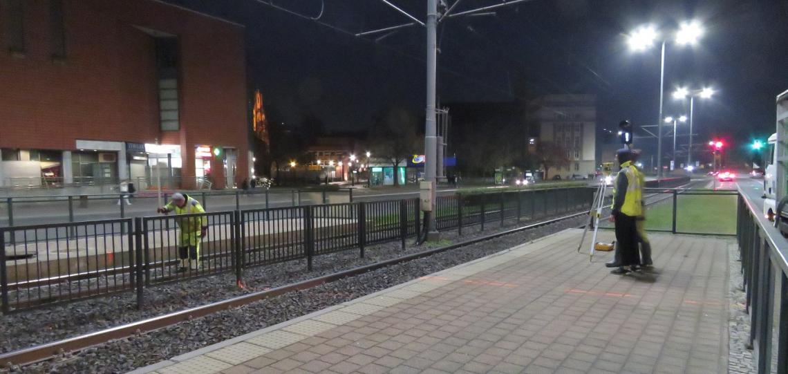
The ending well was located between the tram tracks.
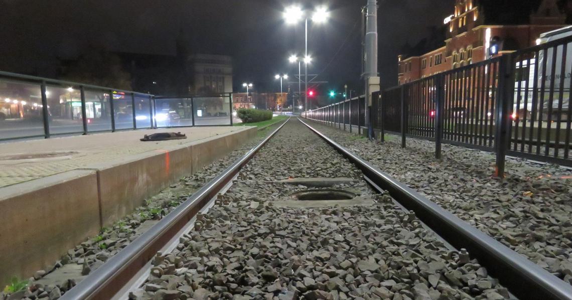
The installation requiring reconstruction ran under a three-lane street and under a tram track. There was absolutely no question of any closure of this node for the duration of the works. The use of any other technology would result in the exclusion from traffic of a significant part of communication routes or even their complete closure for several working days. This would cause a total paralysis of communication in the center of Gdańsk. In addition, any mistake in implementation would result in damage to the soil around the construction site, as a result of which the road surface and tracks would be destroyed. For the above reasons, our Gravity Drilling technology turned out to be the only technology enabling the execution of works in a fully trenchless and safe way for the surrounding infrastructure.
We divided the renovation works into three main stages.
STAGE 1. Preparation of the damaged section of the network for renovation.
We started the reconstruction of the network by filling the damaged sewage pipe with injection grout. We used the GRUNTON DR-1.5 filling compound for this.
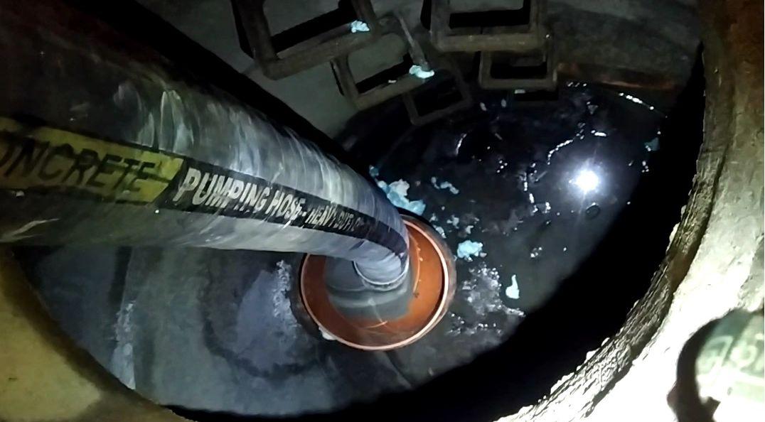
In order for the filling process to run optimally, inlet elbows for the filling mixture were installed on both sides of the damaged sewage pipe before filling.
This ended the first day of construction. The injection grout must set and harden sufficiently to enable the next stage of construction.
It is worth noting that in a similar way, i.e. by using injection grout, we build new sections of the gravity sewage network, when we encounter obstacles such as empty spaces on its route. Overcoming such a hollow space with the drilling head is impossible due to the inability to control the drill during the next step, described below.
STAGE 2. Performing a pilot drilling.
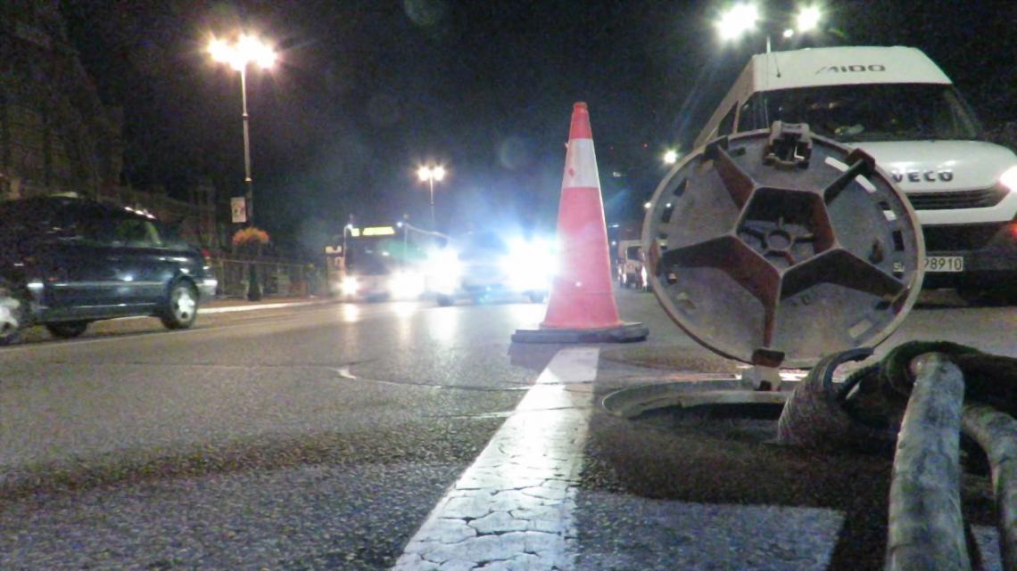
This is the most important stage from the point of view of successful implementation using our technology. The correctness and accuracy of its implementation determines the achievement of a given, designed gravitational fall for a newly built or repaired sewage system. For the duration of the works, at each stage, we excluded from traffic only one left lane, on which there was a manhole to the sewage well.
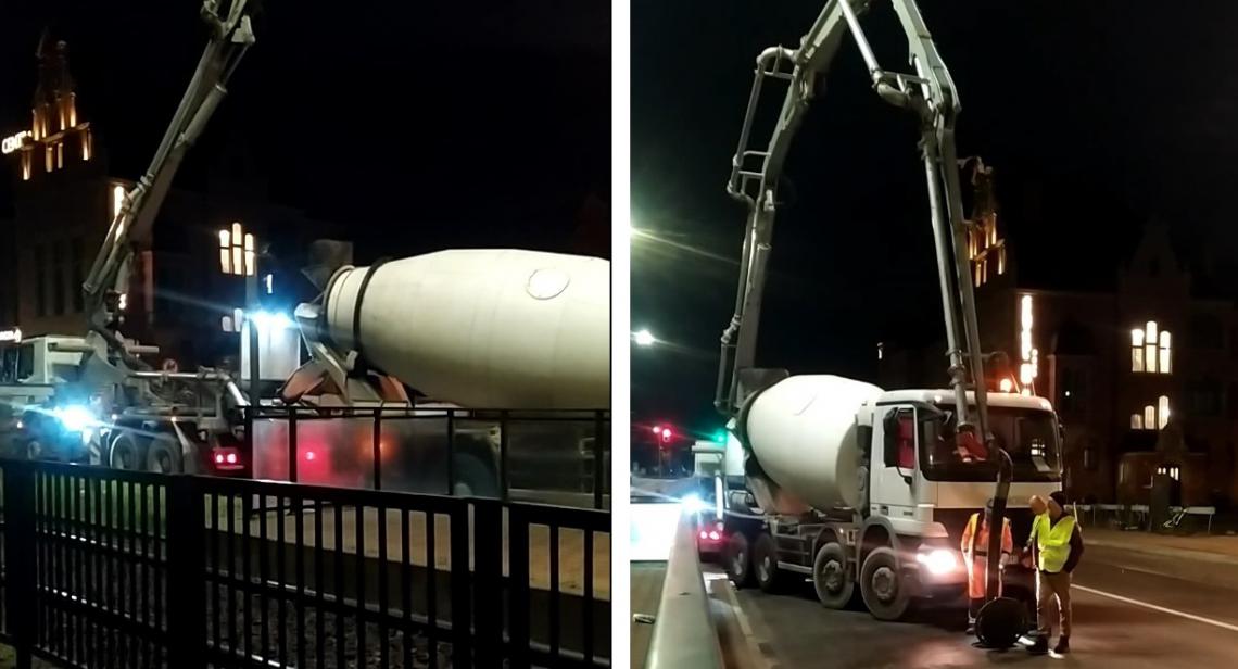
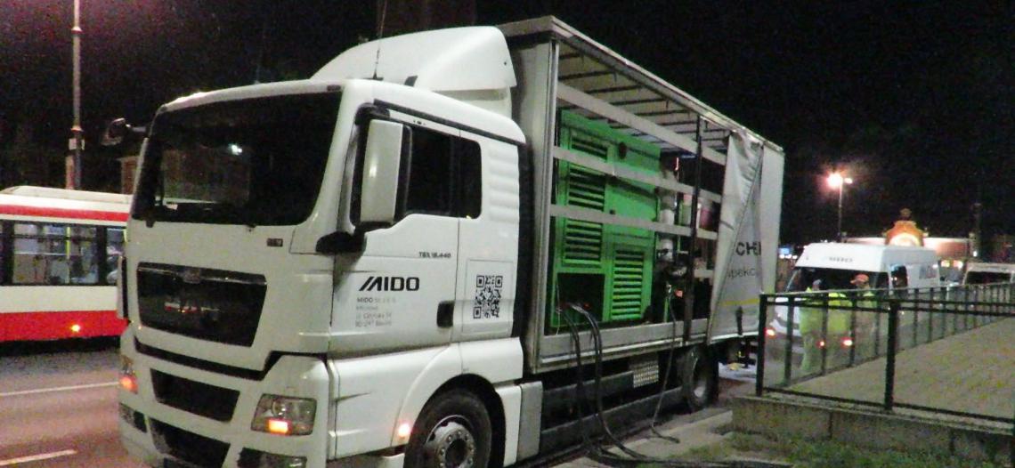
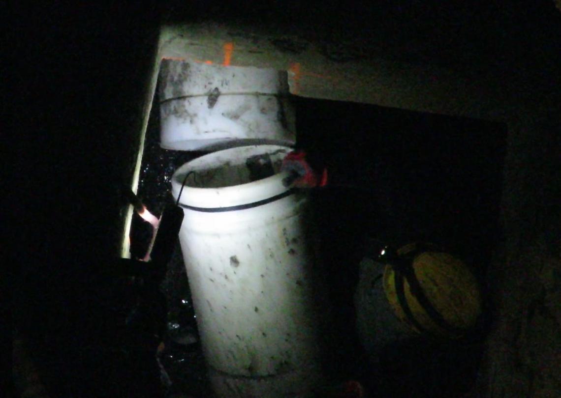
We placed one of our compact technical vehicles in close proximity to the starting well. On it and in it there are all devices, both power supply and directly involved in the performance of work. This greatly facilitates and shortens the construction time.
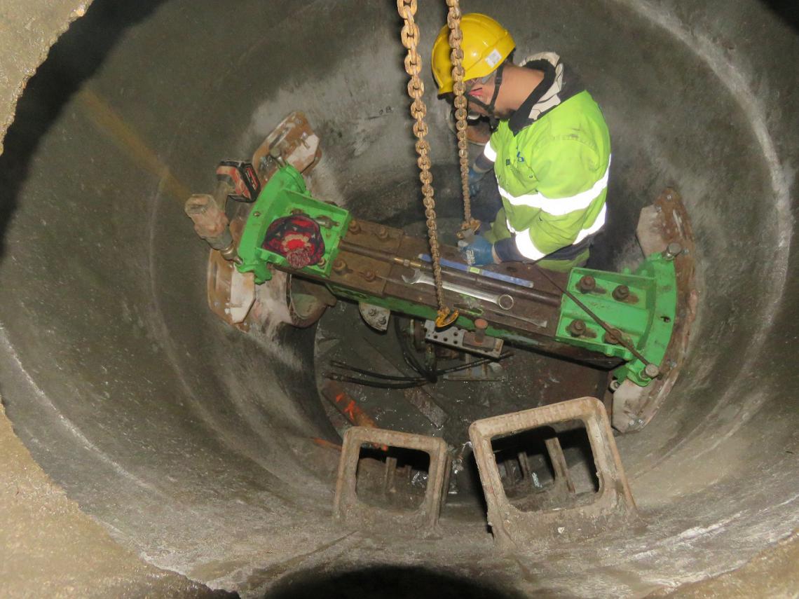
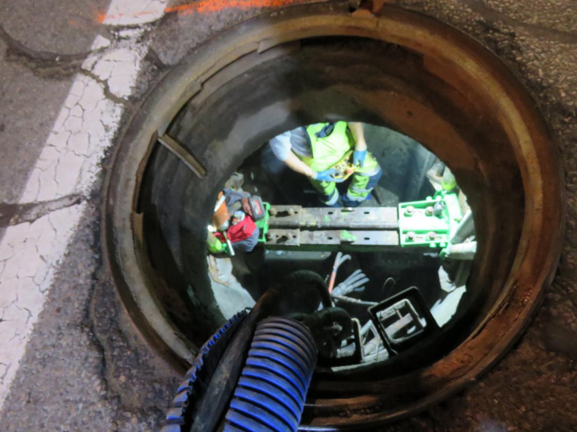
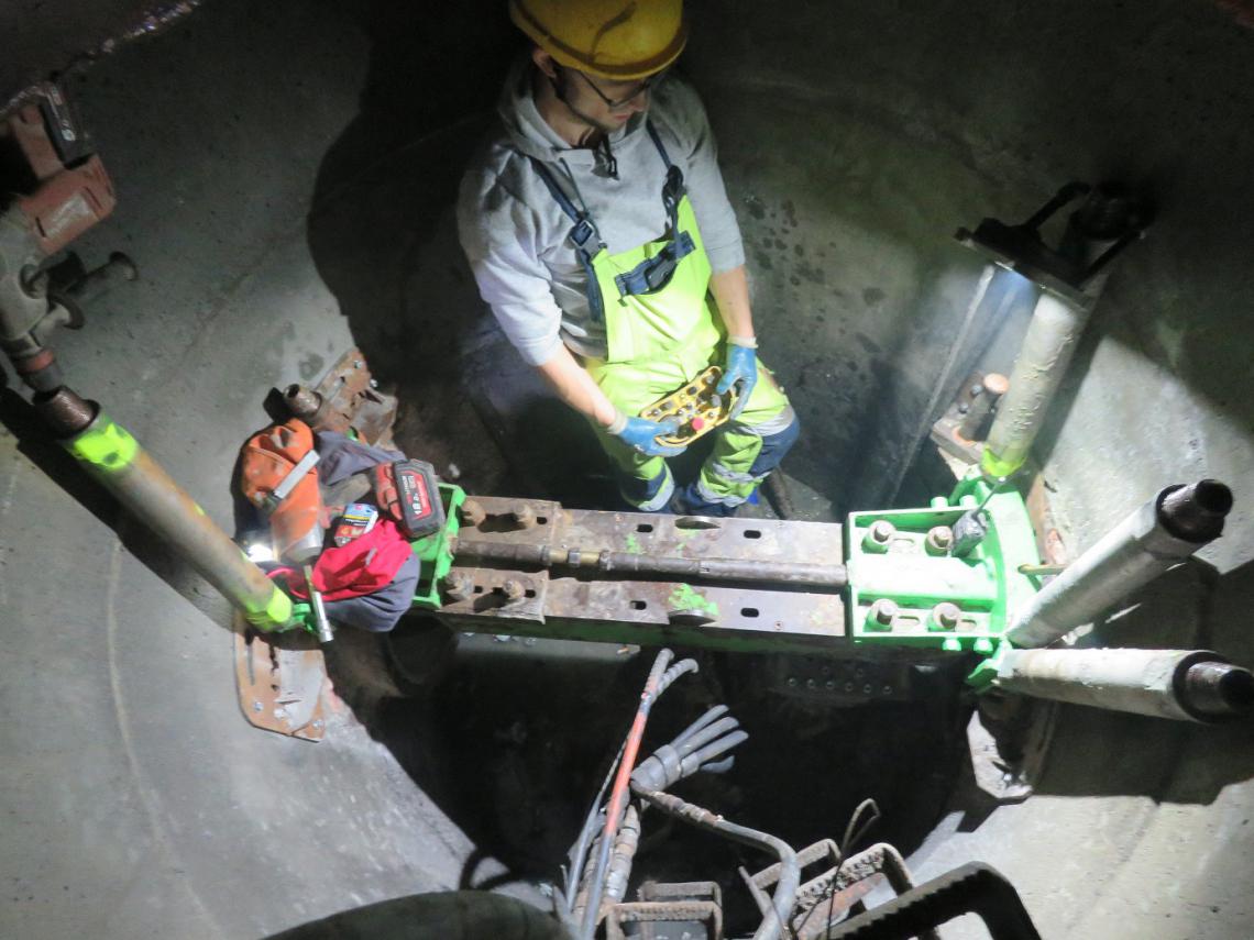
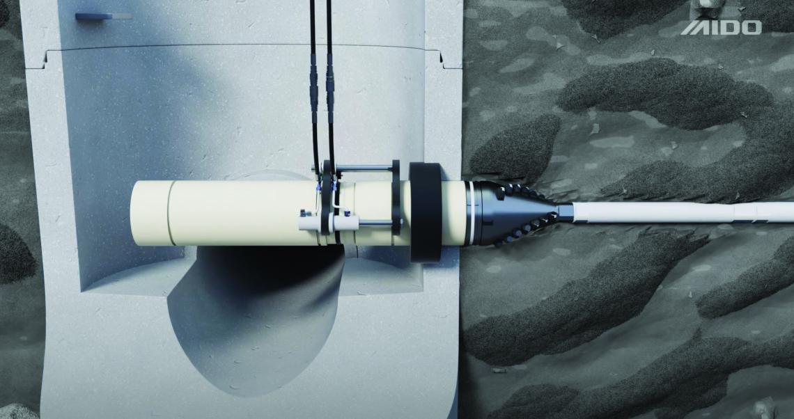
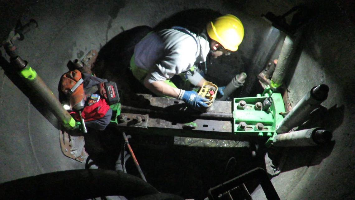
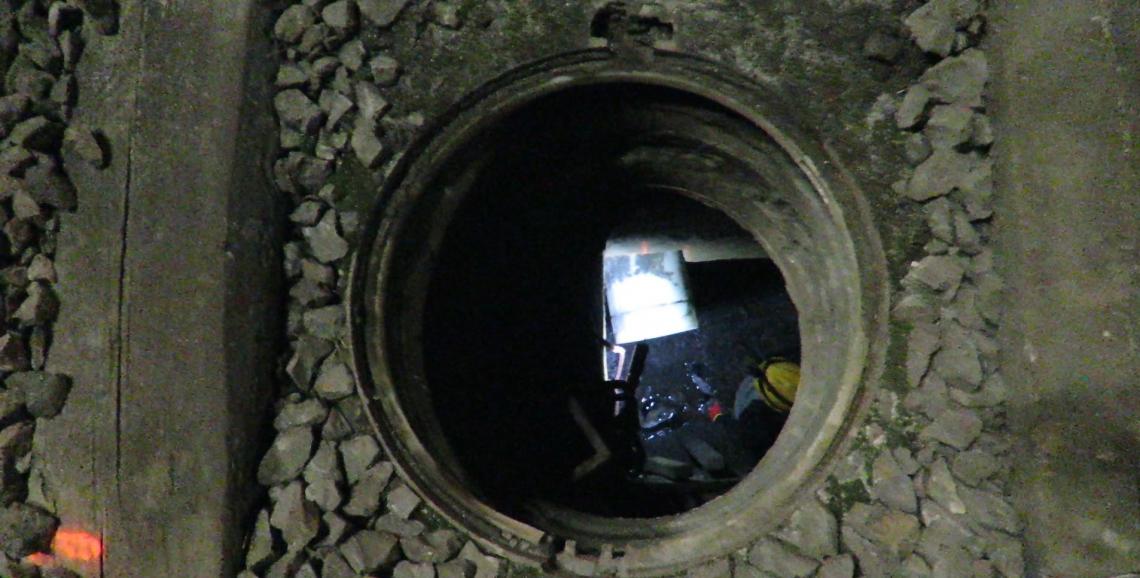
Using the crane installed in the technical vehicle, we installed the drilling machine in the well. Here it was a DN 1500 well. As you can see in the next photos, our technology does not require the dismantling of any element of the existing land development, including the manhole cover. We introduce our drilling equipment in the form of separate elements into the well through a typical DN 600 manhole.
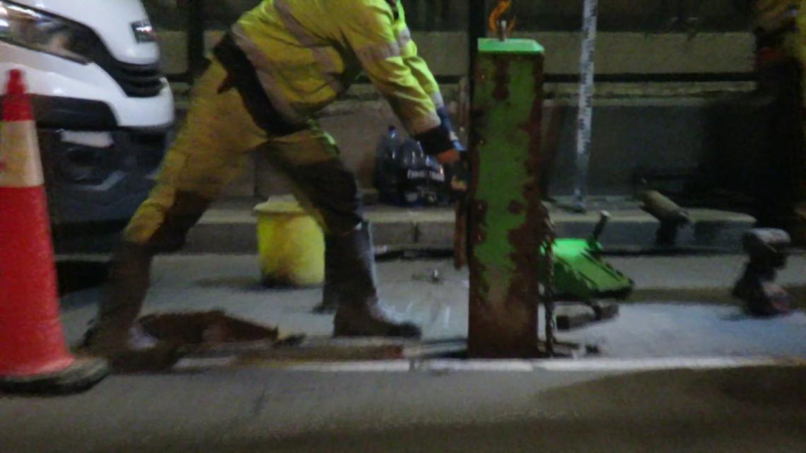
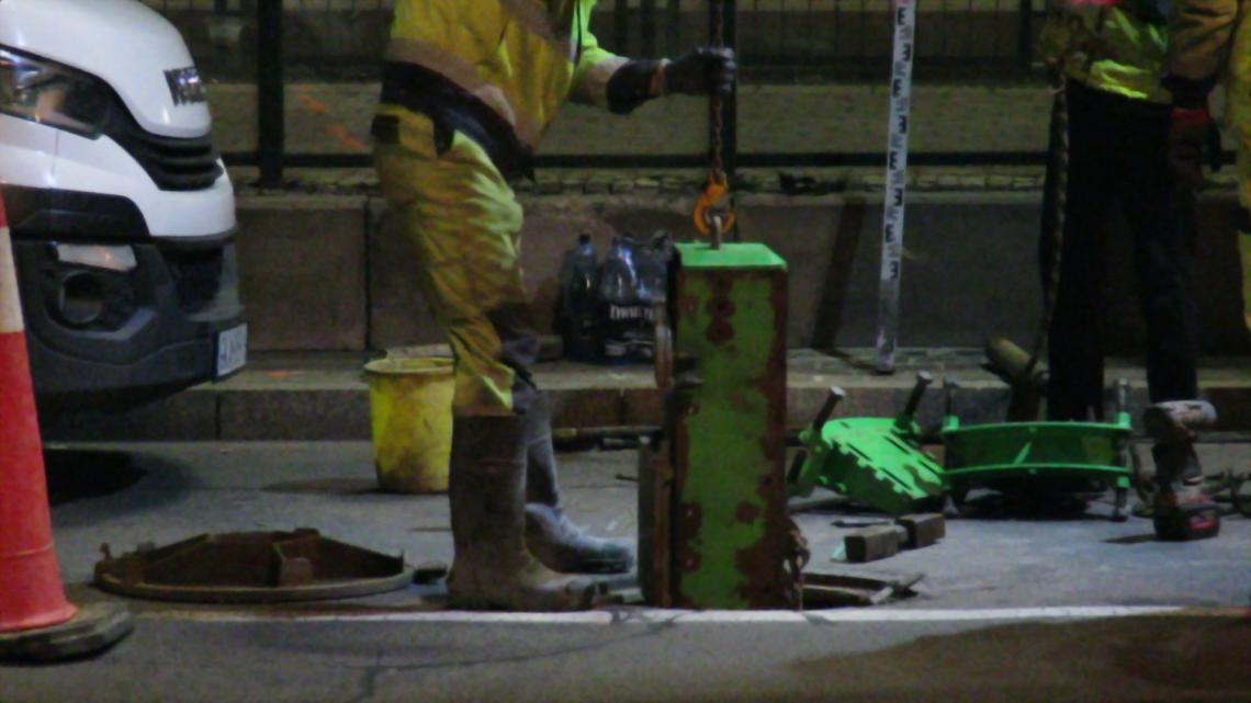
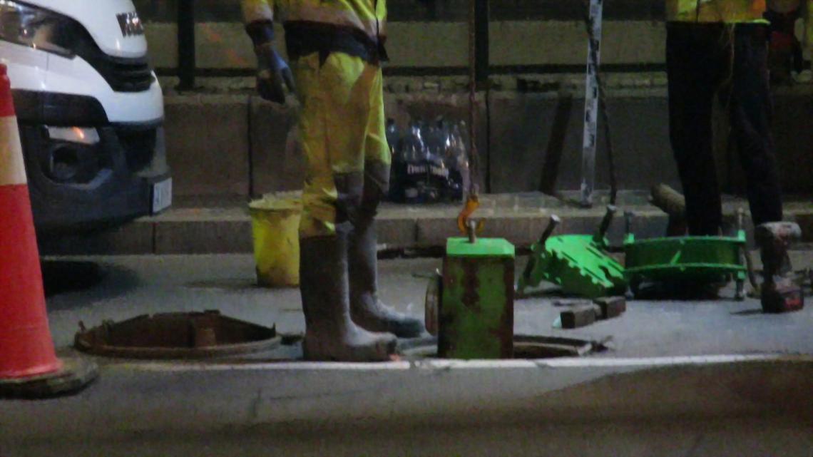
In the starting well, the individual subassemblies of the drilling rig are assembled.
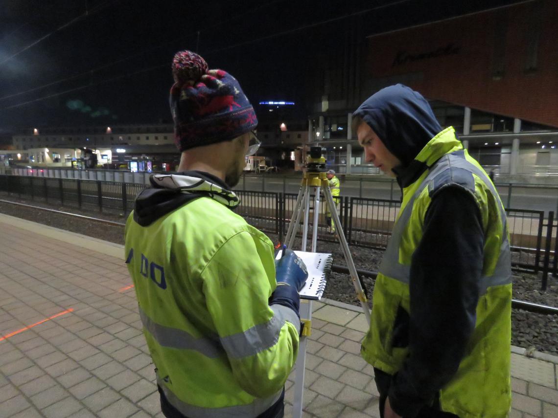
Simultaneously with the installation of the drilling equipment, the appropriate measurements of the drilling depth and direction were made and the drilling route was determined.
Other devices related to the drilling rig, such as the hydraulic power unit and the mud unit, are located on the technical vehicle.
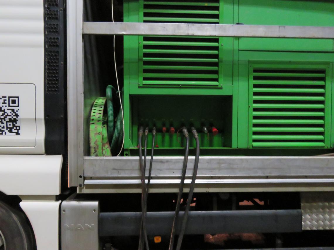
The drilling rig is connected to them with drilling lines and we can start working.
The drilling rig operator is in constant radio contact with a member of the team responsible for the current control of the drilling route. A probe is mounted in the drilling head that sends a signal containing the basic elements of the position, such as the momentary gravitational drop, the depth at which it is located, the position of the element that enables drilling control..
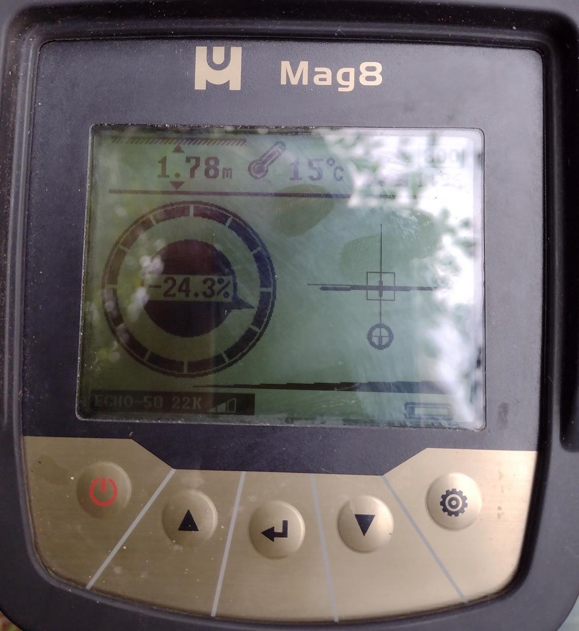
A member of the team supervising the control of the drilling route, using the receiver of radio waves sent by the probe, has access to all relevant parameters of the drilling. This information is provided to the drilling rig operator on an ongoing basis. And the latter, depending on the information received, continues drilling or corrects the trajectory.
Drilling is controlled in the same way as in the case of typical horizontal drilling rigs (HDD - Horizontal Directional Drilling). There is an element on the head that allows to control the drilling.
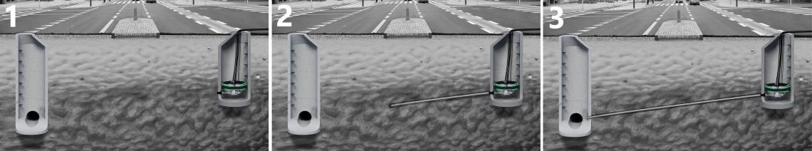
During drilling, the drill head is pushed forward while rotating. In the event of an undesirable change in the drilling direction, the rotary movement of the head is stopped in the appropriate position, while its pushing movement is maintained until it returns to the required trajectory. The following illustrations show a schematic view of the drilling control process.
1 - Drilling. The trajectory is as expected, i.e. pushing with simultaneous rotation.
2 - Unintentional change in bore trajectory. The drill head moves up.
3 - Stopping the drilling and pushing process.
4 - Setting the drilling head in a position enabling return to the planned trajectory.
5 - Pushing the head with rotation turned off. The pressure of the ground on the control element of the head causes the return to the required trajectory.
6 - After the drilling route has been corrected, the rotary movement of the head is switched on again.
It is worth mentioning here that our technology of horizontal directional drilling includes two types of drilling devices. So we have single-drive drilling heads. In this system, we have one rotary drive of the head, responsible for simultaneous drilling in the ground and positioning and possible corrections of the trajectory. This type of head is called a steering fin head and is used in other trenchless technologies such as HDD.
The advantage of this solution is the simplicity of construction and drilling control, which translates into ease of construction. However, an important disadvantage is the difficulty of overcoming hard obstacles. Such a head, encountering a hard obstacle such as a pebble or a fragment of a concrete foundation, will not be able to drill through it and will deviate from the set course. In the vast majority of construction sites, a drilling system with a single drive completely allows for the construction of sewage network elements in accordance with the design and the required gravity slope. However, in places where we expect difficult ground conditions, we reach for a drilling machine with a double drive. In this construction of the machine, we have two separate rotary drives: an internal drive responsible only for drilling in the ground and overcoming any hard obstacles; and an external drive responsible only for controlling the drilling route and possible course corrections.
In the construction of the external drive, we have a special control strip that works in the same way as the fin in a single drive. In the event of an undesirable change in the drilling direction, only the external drive is stopped in a certain position, while the drilling process is continued with the internal drive and the head is pushed. The external drive is held at the specified position until the bore returns to the required trajectory.
Let us return, however, to the description of the renovation of the sewage network at the Gdańsk Główny railway station. The drilling rig operator, together with the rig in the starting well, in consultation with the measurement system operator, continues the pilot drilling towards the final well. The damaged channel has been previously filled with injection grout, so the drilling process is not disturbed by encountering different soil fractions or voids. In addition, there is no fear that a collapse of the ground around the repaired sewer will not lead to a construction disaster.
The operator, adding more drill rods, advances towards the final well. The process proceeds as shown in the schematic illustrations below.
1 - Installation and start-up of the drilling rig
2 - Pilot drilling
3 - Completion of the pilot drilling when the ending well is reached
The end of the second stage takes place when the ending well is drilled
STAGE 3. Rebuilding the damaged network element.
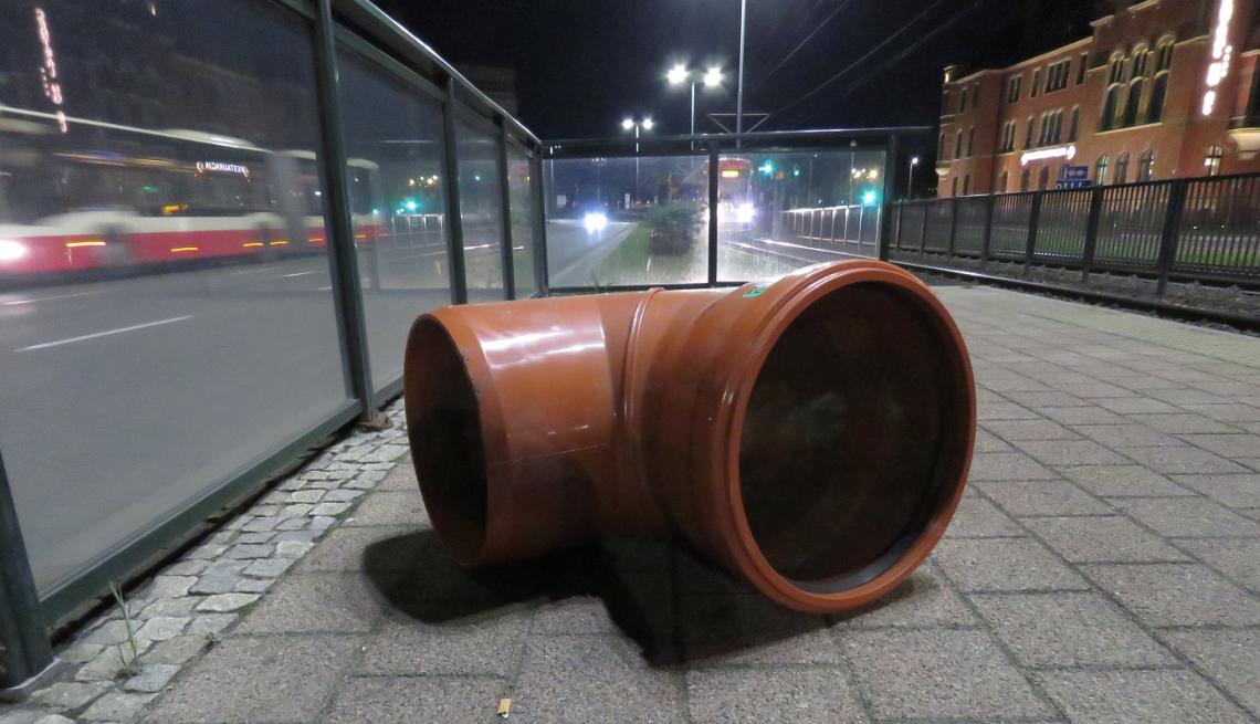
The pilot drilling was performed as planned, perfectly following the trajectory of the damaged pipeline. It was therefore possible to proceed to the last stage, i.e. its reconstruction. PP 400x22.7 pipe modules were used. A series of types of PP pipe modules with diameters up to 500 mm is dedicated to the Gravity Drilling Technology. However, depending on the investor's requirements, the technology allows the use of other types of pipes made of plastics, such as PE, PVC. The advantage of using PP pipes is very high smoothness of the walls, as a result of which we obtain very low flow resistance.
Polypropylene is characterized by very high chemical resistance, which results in a low tendency to overgrow the internal surfaces of sewage pipes during sewage flow. Pipes made of PP work thermally, i.e. they change their dimensions depending on the temperature. This additionally favors the removal of deposits, which, as a result of changes in pipe dimensions, crack and are washed away by the flowing stream of liquid flowing in the pipeline. Another extremely important feature of pipes made of PP plastic is their flexibility. Compared to rigid traditional stoneware or concrete pipes, pipes made of PP are more resistant to mechanical damage, unsealing of the installation, occurring as a result of stresses resulting from the movement of the ground. We have often renovated a network made of stoneware or concrete pipes, damaged as a result of displacements and ground tremors.
But let's get back to the stage of sewerage reconstruction. After reaching the final well with the pilot drill, we drilled through its wall. In place of the pilot drill, a reamer with a diameter of 420 mm was installed, to which the first tube module was attached. The whole thing was then pulled back towards the starting well, while the damaged sewer conduit was reamed and more pipe modules were added. The illustration below illustrates the subsequent elements of this stage.
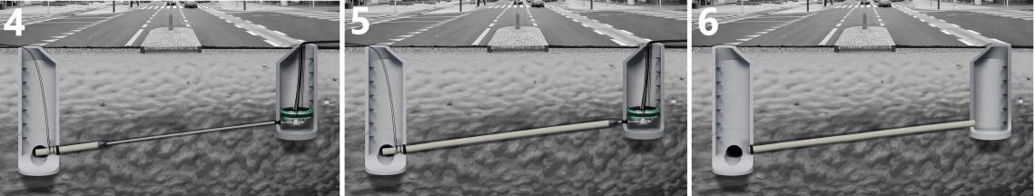
4 - Reaming a damaged pipeline while building and pulling in subsequent segments of modular pipes.
5 - The last phase of pipeline construction, drilling the wall of the starting well.
6 - Network rebuild process completed. Sealing the connection of the pipe with the walls of the well
Another important feature of our standard pipe modules is the very small space required for their assembly. Connecting successive modules is done with the help of a small, compact hydraulic compressor. The process of building a pipeline from pipe modules can take place in an area limited by the diameter of a DN 1000 well. The typical gross length of the module is 700 mm.
In the starting well, the drilling rig operator pulls the pipeline disassembling successive segments of drill rods.
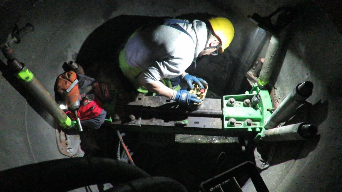
In the ending well, successive PP pipe modules are connected with the use of a hydraulic crimper, while the already constructed section is pulled in towards the starting well.
The last step was to check the quality of the reconstructed pipeline and compliance with the required gravity gradient using a specialized CCTV vision system.
The ordering party accepted the works without making any comments.
It is also worth reading about our other selected projects: